
Extrusion Plants
- Melting Furnace
- Holding Furnace
- Casting Machine
- Billet Area
- Billet Heating Furnace
- Log Hot Shears
- Extrusion Press
- Die Oven
- Quench System
- Hot Saw, Flying Saw and Cyclone
- Puller - Single Puller / Double Puller
- Handling Table and Cooling Area
- Stretcher
- Finish Saw and Cyclone
- Saw Gauge
- Inspection Table
- Aging Furnace
Other Equipment
- Homogenizing Furnace
- Annealing Furnace (Up to 550o C)
- Scrap Bailer
- Extrusion Wrapping Machine
- Anodizing Tank and Sludge Separator

-
General Information Brochure (PDF)
You will need Adobe Acrobat Reader to display the document. Please click on the Adobe to load the program on to your computer.
Download
- A,B
-
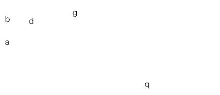
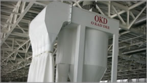
Melting and Holding Furnace
O.K.D. has designed and manufactured a full range of aluminum melting and holding furnaces to support the extrusion system and serve the foundry. Tilting or stationary designs are utilised to suit the application. We use high efficiency combustion technology for the fuel efficientcy. Accurate control of temperature is provided by PLC control systems.
-
 top
top
- C
-
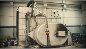
Casting Machine
O.K.D. Casting Machine, installed operation in the vertical mode, consists of tilting furnace together with graphite dies and cooling assembly. When the molten metal flows from the melting-furnace to a holding or casting furnace it will keep a reserve (or "Heel") of molten metal to facilitate the melting of the subsequent charge.
- top
- D
-
Billet Area
The benefit from our billet saw is the reduction of swarf in terms of both weight and volume, the saw enables the billet length to be accurately controlled thereby minimising wastage at the extrusion stage. The billet saw is positioned in front of the induction furnace and replaces pre-cut billet enabling easy changing of the billet length according to the requirements of the section being extruded.
- top
- E
-
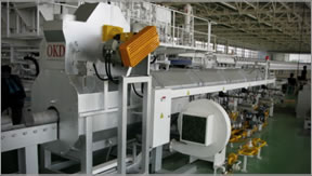
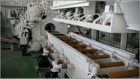
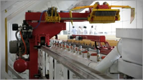
Billet Heating Furnace
The aluminium log/billet furnace is designed for continuous heating of metal before feeding into the extrusion press. O.K.D supply the furnace with a log infeed table and pusher and a log piling table. The furnace is lined with high alumina refractory and the roof is compressed fibre for good insulation. The furnace consists of two primary zones, a heating zone and a recuperation zone. The heating zone is subdivided into three individually controlled sub zones. The hot gasses from the hot zone pass down the recuperation zone, preheating the incoming log before exiting to the flue. The furnace can be either natural gas or LPG
-
 top
top
- F
-
Log Hot Shears
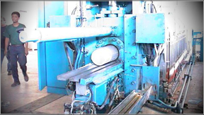
Supplied to order according to the billet size the O.K.D. hot log shear is designed to cut logs into extrusion billet ready for transfer directly into the press. The powerful thrust is sufficient to ensure a rapid cut on the complete range of AA6000 series alloys. The shear action cycle is fast thereby allowing the maximum time for billet heating, an important consideration when feeding a fast press. The billet length is set on the main control console and the log feed is accurately measured before cutting.
The shear comes complete with the billet optimization equipment and software program to control it. It also includes a transfer unit to the press infeed device and billet discard facility.
-
 top
top
- G
-
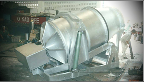
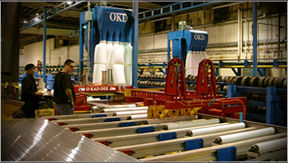
Extrusion Press
- top
- H
-
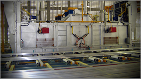
Die Oven
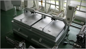
The O.K.D. die oven is a simple, rebust and inexpensive piece of plant designed specifically with the jobbing extruder in mind. It offers fast die heating with good temperature control and uniformity of heat.
The oven comprises two zones which each zone is equipped with a die rack to hold two rows of three dies. Each chamber is separately heated and independently controlled. This enables one chamber to be used as a preheat chamber and the other for heating to extrusion temperature if desired. This is particularly useful when long running batches are being extruded.
The chamber are closed with pneumatically operated lids which slide completely clear of the opening to give unimpaired access for the die crane. Dies are heated by re-circulating air. Elements are connected in parallel so that the failure of one element does not break the circuit. The oven can be supplied fitted for nitrogen protective atmosphere if specified at the time of ordering.
-
 top
top
- I
-
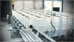
Quench System
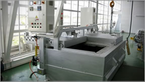
(Under Water and High Pressure Spray Quench)The press quenching of aluminium alloys to produce satisfactory mechanical properties combined with acceptable shape is still considered something of a black art. Quenching may be defined as the process to enable the extruded material to achieve a desired set of mechanical properties. The cooling process may consist of water quenching, either by immersion or sprays. Water quenches are in general getting longer on new plants and where space permits. Cooling may be by high pressure water jets or air water mist.
Air cooling is the simplest, cleanest method and saves money. It will have more effective if is concentrated in the first transfer and cooling position or on the initial table. Air can be delivered from overhead fans, ducted air or undertable fans
-
 top
top
- J
-
Hot Saw, Flying Saw and Cyclone
Hot Saw :
The hot saw is undertable cut design. It cuts the new extrusion from the previous extrusion on or close to the stop mark during the press dead cycle time. The use of a hot saw enables the length of extrusion between the stop mark and the end of the section to be utilized giving about 3 to 4 % improvement in metal recovery.
Flying Saw :
The flying saw is designed to cut the extrusion lengths on the stop mark during the extrusion cycle. It is positioned on opposite the puller side of the leadout table a short distance from the press. As the stop mark emerges from the press the second puller of bypass puller and the flying saw will move down the leadout table, both synchronizing their speed with that of the extrusion and with the cut device in line with the die stop mark. After its cut the saw blade has retracted the flying saw stop
-
 top
top
- K
-
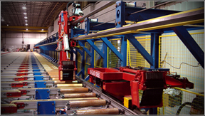
Puller - Single Puller / Double Puller
The main purpose of the puller is to keep extrusions straight and to stop them from twisting and rubbing against each other. It will, with limits, equalise the flow of metal in the various holes of a multi-hole die and also minimize or eliminate the ripple of long edge or long middle due to variations in running speed within a single die hole. The puller can also be used to clear the extruded lengths from press and leadout zone and to position them accurately on the runout table.
OKD pullers consist basically of a wheeled carriage attached a gripper head running on rails mounted at the side of or above the initial and runout tables. The puller works in conjunction with a movable hotsaw or flying saw. Tension is applied to the puller carriage by means of a rope driven from a capstan and idler sheave. The capstan is powered by an inverter driven AC motor or DC motor according to customer preference.
Single Puller :
The single puller working in conjunction with a movable saw can reduce scrap by more than 5%. This is the most utilised puller system throughout the world. It is relatively inexpensive and easy to install and maintenance
Double Puller
Double puller have been developed to meet three perceived needs:
- to keep up with the much shorter dead cycle times of the press.
- to enable extruded lengths to be cut on the stop marks thereby minimizing waste.
- to enable multiple runs from a single billet to be extruded with out a break.
O.K.D. has designed the double puller to use either a flying cut off saw or undertable hot saw according to customer requirements. Puller can be either supplied either "hand over hand" or bypass puller or hand to hand, sometimes referred to as a "hand off" puller.
-
 top
top
- L
-
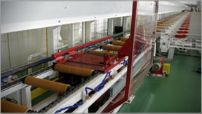
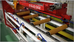
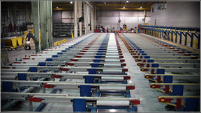
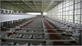
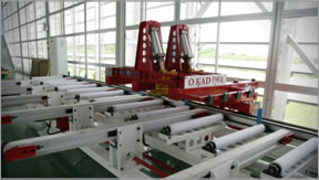
Handling Table and Cooling Area
O.K.D handling table and cooling area including:
- Make up table, short table equipped with rollers covered heat resisting felt, come between the press and the moveable hotsaw. It can be raised and lowered by means of a screw jack to take account of the differences in extrusion height.
- Initial table consists of a substantial steel frame carrying a series of driven rollers covered with heat resisting sleeves. It is designed to work with a puller thus the running speed will be synchronized with the puller running speed
- Runout table consists of a substantial steel frame carrying a series of driven rollers covered with heat resisting sleeves. The frame is capable of being lifted and lowered to facilitate transfer of the extruded sections from the runout table to the transfer belts. the running speed will be synchronized with the puller running speed.
- The initial transfer belt is activated automatically by a signal from the PLC as soon as the run out table is in the down position and will transfer the profiles out of the runout zone and onto the cooling bed.
- The cooling table moves the extrusions from the initial belts through a cooling area by belt conveyors in automatic mode. The belts can be moved forward & reverse by manual operation and activated automatically by a signal from the PLC.
- Stretcher Feed Beltsmove the sections from the cooling table to the stretcher and through to the batch (storage) belts. They consist of a polyester needle felt fabric and incorporate "Pop Up" Rollers.
- The storage tablestores and conveys the extruded profiles from the stretcher to the saw infeed table. It can be operated either automatically or manually both forward & reverse
- Guard fencingis provided for the length of the puller rail and around the puller drives units. The fencing consists of mesh panels supported in angle iron frames. For the guards in the other parts we can supply as customer request.
-
 top
top
- M
-
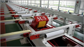
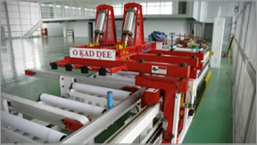
Stretcher
The stretcher is vital and integral part of aluminium extrusion lines. It is located between the cooling table and the batching, or storage table, to straighten the sections before being cut into the required lengths.
O.K.D has deigned an undertable stretcher (sometimes referred to as a "submarine" Stretcher). This amachine is equipped with scroll type jaws to grip the sections during the stretch operation. The headstock is hydraulically operated and applies the tension for the stretch cycle.
The tailstock can be lowered into the stretcher bed for re-positioning according to the length of the extrusion, Either one man or semi automatic operation is normally supplied but for heavily bent or distorted sections, the stretcher can be used by two men.
-
 top
top
- N
-
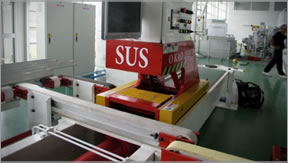
Finish Saw and Cyclone
The O.K.D finishing saw is an undercut design, it includes a cyclone dust collector for effective removal of the chips from the sawing area. The finish saw cuts the extruded profiles to the required customer lengths. The work will be clamped automatically on both sides of the blade before the saw lifts, moves through the work, cutting the sections to the end of the stroke. It then lowers and returns to the start position
This system is normally be supplied with the gauge table comprising a measuring stop. The length is digitally indicated and can be positioned automatically from the saw control desk.
-
 top
top
- O
-
Saw Gauge
As profiles approach the gauge stop, they are detected by photocells which slow down the approach speed and minimise the section impact. This reduces the tendency to deflect the gauge stop and gives accurate profile length. The table lowers to transfer the sections for poading into baskets.
-
 top
top
- P
-
Inspection Table
The saw gauge table comprises a measuring stop and a roller conveyer of polyester felt covered rollers. It takes the extruded sections up to the measuring stop for the saw to cut the required digitally indicated length.
Feed Out & Inspection tableautomatically transports the sections from the gauge table to an inspection area.
-
 top
top
- Q
-
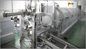
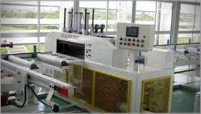
Aging Furnace
The durance is normally supplied double ended so that the charge can be loaded at one end and discharged at the other. This system allows a very quick turn round of charges. The heating system utilises radiant tubes preventing the products of combustion from coming into contact with the charge and the minimum of contamination by unburnt fuel or sulphur.
Heating is also based on the counterflow principle. The direction of flow of the hot air is reversed every 10 to 15 minutes to ensure a more uniform heating of the charge. The furnace is normally heated by natural gas or LPG Construction is such as to minimize heat losses and thus reducing running costs and heat up time.
-
 top
top
;)
;)
;)
;)
;)